Diving into Ansys LS-DYNA’s Fluid Solvers
Computational Fluid Dynamics (CFD) has been part of Ansys LS-DYNA’s Multiphysics offering for more than 10 years. If you are an LS-DYNA user who is curious to learn more, join me as I take a closer look at this capability and explore how it can be used to accelerate product design and development.
Ansys LS-DYNA is the leading solver for non-linear dynamic structural simulation, used by the global automotive industry for crash safety predictions. The explicit solver is the core foundation of the code; however, LS-DYNA offers much more: explicit and implicit solvers for thermal, acoustics, discrete elements, electromagnetics and fluid flow. All the solvers are coupled, making LS-DYNA truly a one-code multi-physics solver.
In a previous article, I discussed how LS-DYNA’s implicit solver can be used for static and frequency domain analysis. Using LS-DYNA’s CFD capability is another example of how we can get more from the code.
Two fluid solvers are available in LS-DYNA; CESE* for compressible fluids and an incompressible fluid solver (ICFD). For many engineering applications such as external aerodynamics of a vehicle, or processes involving liquids like cooling or mould filling, the incompressible fluid solver is a good choice. By assuming the fluid is incompressible, the Navier Stokes equations can be simplified and solved to predict fluid velocities and pressures accurately for Mach numbers less than 0.3 (ref.). In this article I will focus on the incompressible solver.
*Conservation Element/Solution Element method
There are many advantages to using the ICFD solver in Ansys LS-DYNA in addition to its multi-physics coupling, including:
- Automatic meshing of the fluid domain
- Full fluid / structure interaction
- Newtonian and non-Newtonian fluid models
- Steady-state and transient flow prediction
- Range of turbulence models including RANS and LES
- Free surface and multi-phase analysis
- No additional licence cost (subject to licence agreement)
Additionally, the ICFD solver is fully supported by the Oasys LS-DYNA Environment, including a dedicated set-up tool in Oasys PRIMER and specialised visualisation tools in D3PLOT, to guide the user at every step.
Making Life Less of a Drag
Some years ago in Arup, we investigated the ICFD solver for external aerodynamics. Using the DrivAer benchmark geometry, we were able to verify that Ansys LS-DYNA could predict values for drag coefficient (Cd) and pressure coefficient (Cp) that compared well with both experimental results and a reference CFD code (see figure below). Building on this validation, we used the ICFD solver to explore the aero-elastic response of exterior surfaces to impinging airflow, which can cause a “flutter” phenomenon.
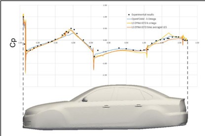
Image source: Comparison of pressure profiles on centreline of DrivAer model
Flutter is aero-elastic instability of an exterior surface, due to forcing from the airstream and flexibility of the surface causing visible oscillation. This undesirable condition may only be found at a late stage when vehicle prototypes are tested. Design changes to address the issues can therefore be costly and impact timing.
Using simulation earlier in the design process can help to avoid this situation. The key enabler in the ICFD solver is its ability to couple the fluid flow solution with the structural solver, because it is the resonant structural response in tune with the fluid forcing that leads to flutter. A traditional CFD approach that does not include structural coupling may miss the phenomenon completely. Our work demonstrated the concept on simple bonnet and spoiler models, showing how LS-DYNA can offer deeper insight.
Keeping Your Distance
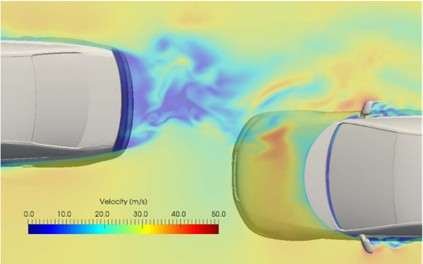
In another study, we investigated the effects of air flow over a vehicle “platoon”. A platoon is a moving group of vehicles that are closely spaced, enabled by vehicle-to-vehicle communication and sensing. Platoons of vehicles may use less energy to move through the air and take up less space on the highway. Understanding the airflow over the platoon is critical for safety and energy efficiency. By modelling different platoon configurations in Ansys LS-DYNA, we could explore the effects, opening the door to further optimisation.
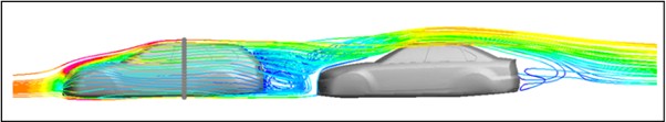
Image source: Velocity streamlines plotted in Oasys D3PLOT, over two closely spaced vehicles
The study showed how results from the ICFD solver could provide insight into the complex interaction of vehicle spacing and body shape (see figure above). An additional next step with the ICFD solver could be the prediction of structural response to the platoon effects, e.g. buffeting from the close spacing of the vehicles. Both papers provided verification that the ICFD solver is a viable tool for external aerodynamics with attractive benefits, for example, rapid model generation using automated fluid domain meshing and structural interaction.
Keeping Cool When Things Heat Up
Since this work, Battery Electric Vehicles (BEVs) have gained significant market share, driven by the UK’s 2035 zero-emission target. Our services have expanded in response; beyond structural safety and durability we now support clients in battery system development using Ansys LS-DYNA. Its most direct application is in simulating structural tests required by safety standards: shock, crush, vibration, and fatigue. But LS-DYNA also enables thermal analysis, battery cooling design via the ICFD solver, and exploration of thermal runaway.
Cooling is critical in large battery packs, typically achieved with a closed-loop liquid system that extracts heat from cells and dissipates it through exchangers. The cooling plate, often a thin embedded layer, must be carefully shaped to ensure uniform coverage and avoid hotspots that impair cell performance. Simulation helps optimise geometry, flow distribution, and thermal efficiency under peak loads.
LS-DYNA’s coupled electromagnetic, structural, thermal, and ICFD solvers can model the physics of battery cooling. Randles Circuits simulate cell electrochemistry, linking current flow to external load and internal resistance. This generates ohmic heating, which is conducted into the cooling plate and transferred to the fluid via conjugate heat exchange.
The Oasys LS-DYNA Environment features new tools to aid in the preparation of battery models. Oasys PRIMER’s Battery Set-Up Tool enables quick definition of Randles Circuit parameters, cell arrays and a choice of busbar configurations.
In the example shown below, two cell stacks are bonded to a cooling plate with thermal adhesive. Heat from the cells is conducted into the cooling plate and passed to the fluid via conjugate heat transfer. In this model, the fluid flow is solved as a steady state before coupling with the thermal solver, based on the assumption that the flow dynamics are unaffected by thermal loading. In this example, simultaneous plotting of fluid velocity and temperature was realised in Oasys D3PLOT.
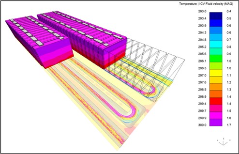
Image source: Ansys LS-DYNA coupled ICFD-Thermal analysis of battery cells and cooling plate
Fluid flow analysis is also crucial for simulation of thermal events. Thermal runaway is a complex process involving rapid breakdown of cell components at high temperatures, generating gas. Cells and enclosures are vented to avoid pressure buildup, but hot gases can travel through the pack, interacting mechanically and thermally with surrounding structures. This may cause distortion or failure of sealed areas, compromising venting. If heat spreads to adjacent cells, they may runaway and vent, escalating into full pack runaway.
Research by Ansys into gas generation and venting includes the Continuum-based Particle Gas method. When combined with Randles circuit modelling, LS-DYNA offers a robust framework for simulating thermal runaway scenarios.
Going with Flow
Aluminium castings play a growing role in lightweight BEV body structures, where optimising stiffness, durability, crashworthiness and mass is critical. Yet castings often show non-uniform mechanical properties, making it essential to represent their geometric variation in crash simulations.
Much of this variation stems from the casting process itself; cooling rates, turbulence, and shrinkage all influence final properties. By simulating the process, it is possible to predict property distribution and refine casting configurations such as runner and gate positions. Can we use Ansys LS-DYNA’s ICFD solver to simulate casting processes?
To investigate this question, we replicated a benchmark test from the University of Birmingham. In this test, a simple rectangular mould was filled with a gravity feed, using a bottom-gated runner and tall sprue designed to induce turbulence. During the test, X-ray film captured mould filling, allowing direct comparison with LS-DYNA’s results.
The results were very encouraging; LS-DYNA could correctly reproduce the key results from the test:
- Correct time to fill the mould (2 seconds)
- Correct direction and size of the fountain from gate into mould
- Accurate resolution of fluid dynamics at the junction of sprue and runner
The animation also shows the variation of temperature in the molten aluminium, giving an extra dimension to the visualisation of the mould filling.
A more complex model is shown below, with multiple gates. Although still a relatively simple example, it is clear to see how this technology could be developed to provide useful insight into the casting process and the properties of the part itself. For high-speed, high-pressure casting processes, the effects of compressibility should be considered.
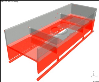
Image source: Casting analysis with multiple gates
Conclusion
Ansys LS-DYNA’s ICFD solver is a powerful, versatile tool for complex fluid problems and structural interaction. Fully integrated with LS-DYNA’s multi-physics solvers and available at no extra licence cost, it delivers high-performance results and is ready to use for any existing LS-DYNA user.
With the Oasys LS-DYNA Environment, you can rapidly build models in Oasys PRIMER and dive deep into results using D3PLOT’s specialised analysis tools. There is no need to wrestle with complex setups or post-processing.
Ready to elevate your simulations? Start exploring ICFD today. Whether you’re optimising thermal systems, designing cooling circuits, or investigating fluid dynamics, LS-DYNA has the tools, and you have the control.
Simon Hart

Simon Hart leads the Product Engineering Practice in Arup’s Technical Specialist Services Portfolio (UKIMEA). He has 30 years of experience in the use of Computer Aided Engineering in vehicle design and leads teams of engineers working on new electric vehicle projects.
Simon works closely with the Oasys LS-DYNA Environment software business and provides a link between the development of digital products and their application on engineering projects.
Related News
-
-

Walking Safe: The New Era of Pedestrian Protection with CAE
-
How a one solver approach can streamline your team’s workflow